|
WLAN System Setup
WLAN system setup typically involves an evaluation of communication requirements, location assessment (site survey), network design, equipment configuration, and system testing.
Communication Requirement Analysis WLAN communication requirements include the location, data transfer rate requirements, and number of users.
The physical location areas for the WLAN should be reviewed for the ability to provide services to users. What are the desired operational areas such as workspace, meeting rooms, and courtyard areas.
The type and amount of data transfer requirements should be reviewed to determine the amount of data transfer per user that will likely occur in each of the desired areas. For example, the required data transmission rates for graphics animators is likely to be much higher than the data transmission requirements of data entry order processor users.
Number of users in each area along with their usage periods should be reviewed to determine the peak demand that will be. This will determine if more access points or high-frequency systems are required for high-capacity data transmission needs.
Network Design WLAN network design is the process of performing a site survey, identifying equipment (components), how they need to be interconnected, software, and configuration requirements.
A site survey is performed on physical location(s) prior to installing equipment or a radio antenna system to determine radio coverage boundaries. In some cases, test transmitters may be installed and personnel may walk through the coverage areas and record signal levels. This determines the actual radio coverage areas/boundaries as existing structures and obstacles affect them.
The physical mounting and cable connection options are then reviewed for each location. Access points are relatively small and light so they can be mounted on or in ceilings, walls, or on poles. Access points require cables for data and power. If power is provided locally, it will require a transformer. Optionally, low voltage power may be supplied directly through (or in addition to) or along with data lines.
The radio coverage range of a WLAN system depends on the type 802.11 system, the transmitter power level, antenna types, objects that are located between the WLAN devices. A typical WLAN device generally provides a range of up to 150 to 200 feet inside wood buildings and up to 1,000 feet out- side without any objects located between the radios.
Because the WLAN system will automatically change its modulation/access technology based on signal quality, there is a tradeoff between data transmission rate and range (distance from the access point). The result is a gradual decrease in data transmission rate as the distance of the access device from the access point is increased. For example, an access device that is transmitting at 11 Mbps that is located within 200 feet may decrease its data transmission rate to 5.5 Mbps as it reaches 400 feet. As the distance increases to over 500 feet, the data transmission rate may drop to 2 Mbps.
There is also a shorter range when operating on a higher frequency. This has to do with the losses and way radio signals at 5.7 GHz propagate compared to the ways that signals at 2.4 propagate.
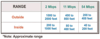
Figure_WALN_23 shows the relative range of WLAN systems. This table shows that if the power level is the same, the distance a WLAN access point (AP) can communicate is generally reduced by higher data rates and higher frequencies. In this example, an 802.11 2 Mbps AP has a range of approximately 1000 feet. This is reduced to approximately 400 feet for an 802.11b 11 Mbps system. This is reduced to approximately 200 feet for a 5.7 GHz 802.11a system.

Figure_WALN_23: WLAN Range Table
Equipment Installation WLAN equipment installation is the process of mounting access points, installing data and power cables, and connecting data routing equipment such as hubs or bridges.
Access points can be mounted on walls, ceilings, and to other objects that have a location that can provide radio coverage. Access points typically have a wired Ethernet data connector (8 pin RJ-45) and a power supply input. The power supply input may be locally provided or it may be provided from a central location that has a backup power supply in the event of electrical power loss.
In some cases, the Ethernet data cables may be used to supply power to the access point. This is possible because typically Ethernet data lines only use 2 pair (4 wires) for data (transmit and receive pairs). This allows for the use of an inline power patch panel to insert power (typically 48V) on the unused wires on a data cable.
Equipment Configuration WLAN equipment configuration is the process of installing the software and configuring the available parameters that control the basic operation of the access point or access device.
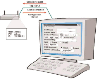
Figure_WALN_24 shows a typical equipment configuration screen for a WLAN system access point. This example shows that a local computer is communicating with an access point. The computer sends a HTTP connection request of http://192.168.1.1 (the default address for most access points) via a standard Internet browser. The access point receives the connection request and returns a login screen (not shown) to the computer. The user then logs into the device using User: Admin and Password: Admin (the default login for many access points). The access pint then returns a screen similar to one shown in the diagram. The user can then enter the settings to configure the access point.

Figure_WALN_24: Wireless LAN Equipment Configuration
Security Setup Network security is the processes used within a network to validate the identity of users (authentication), access control of services (authorization), and information privacy protection (encryption).
Figure_WALN_25 shows a typical equipment configuration screen for a WLAN system. This example shows that the access point and laptop computer have both enabled WEP security. A pass phrase of “wlansecurity” has been used in both devices to create a key “BZ6EA783510E0AC7EA7E” that is used to encrypt the information transferred between the computer and the laptop device. Only devices with the same key will be able to decode the information that is sent between the devices.

Figure_WALN_25: Wireless LAN Security Setup
System Testing WLAN system testing is the process of measuring the operation and performance of the WLAN system in during normal, stressed, and in partially failed conditions. WLAN testing typically includes access testing, radio coverage validation, and data transmission rates.
Testing usually begins with the validation of basic feature operation in normal conditions. Next comes performance testing under stressed (heavy load) conditions to ensure that the system can provide the services under high- usage conditions. Finally, operational testing under unusual conditions such data link loss or partial system failure determines how the system will respond in emergency or disaster conditions. Disconnecting data links or installing devices that have a specific type of failure may perform this.
Dual Band Dual band products are capable of operating on two frequency ranges. The use of dual band products allows users to roam into coverage areas of different systems. For example, a user at the office may access the system at the office on 5.7 GHz and they may access the Internet at 2.4 GHz when they are using the WLAN in a coffee shop.
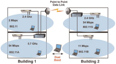
Figure_WALN_26 shows how a dual mode WLAN device may operation. This diagram shows a WLAN card that can operate at 2.4 GHz and 5.7 GHz. In this example, the WLAN card can access the 802.11b 2.4 GHz wireless LAN in building 2 and the 5.7 GHz wireless LAN system in building 1.

Figure_WALN_26: Dual Band Wireless LAN
|

