|
Basic Operation
The WLAN system operates by coordinating the access to the radio channels and sending packets of data between wireless access devices. Packets of data that are sent within the WLAN system must contain enough addresses and control information to allow them to reach their destination. Packets may be sent directly between units (independent mode) or they may travel through a backbone network (distributed mode). Association of devices with access points (APs) keeps track of where devices are operating and the addresses assigned to reach them.
Addressing Addressing in a WLAN system consist of addresses of devices that are part of the WLAN system. These are called medium access control (MAC) addresses. Each device in the WLAN system including stations, access points, and routers has its own unique 48 bit medium access control (MAC) address (also known as a link address).
Each data packet that is transmitted in the wireless LAN contains multiple MAC accesses. These include the source address (SA), destination address (DA), transmitter address (TA), and receiver address (RA). The source address is the MAC address of the device that originated the packet. The transmitter address is the address of the device that sends the packet into the wireless medium. The receiver address is the MAC address of the device that receives the wireless packet. The destination address is the MAC address of the last device in the system to receive the packet.
Figure_WALN_12 shows the frame structure for an 802.11data packet. This diagram shows the packet holds up to 4 MAC (Ethernet) addresses and contains a medium access control (MAC) header and a variable length frame body that holds the data. The data body can vary from 0 to 2312 bytes. The data packet also includes a frame check sum (FCS) to check the packet for transmission errors. This diagram shows that the MAC header is divided into a frame control field (type of frame) contains up to 4 address (used for source, distribution, and destination packet routing) and it contains a sequence control to identify each frame in a sequence of frames.

Figure_WALN_12: 802.11 Packet Frame Structure When Internet protocol (IP) addressing is used, the IP address of the end device (such as a laptop or PDA) is mapped (temporarily associated) with the MAC address of the station. The IP address and its data payload are simply carried by the WLAN packet to the destination MAC address (probably a gateway to the Internet).
Medium Access Control (MAC) Medium (radio) access control involves sensing activity, timing, exponential backoff, and retry limits. Before WLAN devices can transmit, they must listen to radioactivity around them to determine if they are allowed to transmit. Some of the radioactivity includes control messages that define time periods (interframe spaces) where devices are not allowed to transmit because other devices are transmitting or will be transmit during those periods. If a device listens and hears no radioactivity or reserved interframe periods, it can attempt to transmit. If the device does not hear a response to its initial transmission, it will delay its next transmission an amount of time each time it attempts to transmit (exponentially). Devices also have limits on the maximum number of times it can attempt to access (limited number of retrys) other devices. This MAC process removes the possibility of all devices attempting to access and reattempting to access other devices at the same time.
The methods for controlling access to WLAN systems may be random (“contention based”) or assigned (“non-contention based”). The operation of a WLAN system can centralize, distributed or a combination of the two. When the operation of the network is random, it is called distributed coordinated function (DCF). When the operation of the network is coordinated, it is called the point coordination function (PCF).
DCF allows the independent operation (distributed access control) of wireless data devices (stations). In DCF contention-based system, communication devices randomly request service from channels within a communication system. Because communication requests occur randomly, two or more communication devices may request service simultaneously. The access control portion of a DCF session usually involves requiring the communication device to sense for activity before transmitting and listen for message collisions after its service request. If the requesting device does not hear a response to its request, it will wait a random amount of time before repeating the access attempt. The amount of random time waited between retrans- mission requests increases each time a collision occurs.
DCF mode is a peer-to-peer network where the temporarily wireless network that has no server or central access point, hub, or router. Since there is no central base station to monitor traffic or provide Internet access, the various signals can collide with each other.
Figure_WALN_13 shows how a distributed WLAN system allows units to independently request and transmit data. Using a carrier sense multiple access (CSMA) protocol, WLAN data terminals listen for activity in the radio channel before starting to transmit. If there is no channel activity, the WLAN data terminal can begin to transmit. It will then listen to hear a response to its transmitted signal. If it does not hear a response within a pre-defined time period, it will stop transmitting and start the channel access process again (listen then transmit).

Figure_WALN_13: Distributed Access Control
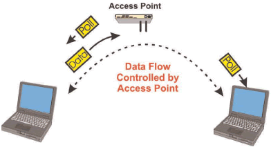
PCF allows the coordinated operation (assigned access control -Infrastructure Mode) of wireless data devices (stations). In PCF contention free system, communication devices wait until they receive a polling message before they transmit any information. Because a master host coordinates the transmission of all the devices within its networks, no device will transmit at the same time (contention free). The access control portion of a PCF session usually involves requiring the communication agreeing to listen to a single host before transmitting any data. To confirm transmitted data has been successfully received; the polling message will usually include information about the status of packets that have been received. If the sending device does not receive a confirmation of transmission in the polling message, it will retransmit the data again after it receives another polling message.
Figure_WALN_14 shows a wireless LAN system that uses a point control function (PCF) that requires each of the access devices to wait until they hear a poll request before they can transmit. When a station receives a token from a serving station (such as an access point), it may respond to the poll request with the information it has to transmit. The use of the PCF mode ensures that channel collisions do not occur. This allows the serving station a guarantee a specific data transfer (data flow) to specific stations. This guaranteed data transmission rate is important for real time communications (such as voice or video).

Figure_WALN_14: Point Control Function (PCF) It is possible to combine the benefits of distributed (DCF) and controlled (PCF) access into one system. The combination is in the form of repetitive time periods that are allocated for DCF and PCF. By combining these processes, it is possible to guarantee data transmission for real time services (such as voice) and permit random access for temporary communication (such as direct connections between laptop computers)
To control the overall flow of packets in the 802.11 system control packets (control frame subtypes) packets are used. These control packets include Request to send (RTS), Clear to send (CTS), Acknowledgement (ACK), Power save poll (PS-Poll), Contention free end (CF-END), and Acknowledgement end (CF-END+ACK)
The RTS packet is used to inform stations that can hear a transmitter the amount of time of a packet that is coming (time duration) to help them avoid packet transmission collisions. The CTS packet is transmitted from the station that is identified in the RTS packet so that other stations know a packet transmission will occur. The ACK packet is used to confirm packet transmission has been successfully received. The PS-POLL packet is used to request the transmission of packets that may have been held during a power saving hold mode. The CF-END packet and CF-End+ACK packet is used to unblock the restriction to transmit during a contention-free period.
Association Association is the process of registering with a system to allow information to be transmitted and received with a device or system. Association in a WLAN systems it the process of registering a wireless data device (station) with a specific access point (AP) that is part of a wireless local area network (WLAN) system.
To allow devices to determine which radio coverage area and device they are communicating with, beacon messages are periodically transmitted (broadcasted) from devices to identify their device and/or network name.
During the installation process for most wireless networks, you need to enter the network name or Service Set Identity (SSID). Different network names are used when setting up your individual computer, wired network or workgroup. The SSID is a 32-character unique identifier attached to the header of packets sent over a WLAN can differentiate one WLAN from another. All access points that are part of a specific WLAN must use the same SSID. A device cannot join a WLAN unless it can provide the unique SSID assigned to that system.
The SSID does not have to be broadcasted by the system. If you have set the SSID in the access point and end user station(s), they can communicate without providing the SSID for others to see.
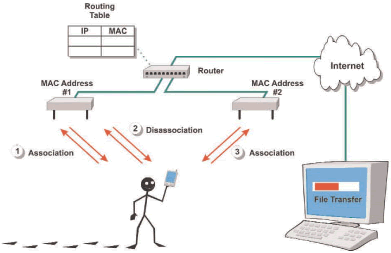
Association allows users to move seamlessly (roaming) from one AP coverage area to another with no loss in connectivity. When a WLAN station first senses an access point, it associates with the AP. When a station leaves an AP or wants to transfer to a new AP because the signal quality is better, it disassociates with the AP. This releases resources and allows the system to hold or reroute packets to the new AP that the station associates with next.
Figure_WALN_15 shows how an 802.11 WLAN system can use the association process to maintain connections between devices as the wander between access points (APs). In this example, a user is communicating with a WLAN system using a personal digital assistant (PDA). When the PDA senses WLAN access node 1, it sends a request for association message to the WLAN access point (AP) 1. AP 1 can then update the router as to the availability of the user in the WLAN network. As the user walks out of range of AP 1, The PDA sends a disassociation request to the system. This allows AP 1 to release the PDA identification from its memory. When the PDA senses AP 2, it transmits an association request. This example shows that the association of the PDA with AP 2 allows information from a distant computer to reach the PDA.

Figure_WALN_15: 802.11 WLAN Association
|

